Komatsu Shop Manual

Sunday, April 10, 2022

HD785-7 POWER TRAIN 1-3 : Transmission

HD785-7 POWER TRAIN 1-3 : Transmission

 Compatible Unit Serial Number : 7001 and up 


STRUCTURE, FUNCTION
AND MAINTENANCE STANDART
for
POWER TRAIN (Part 1.3)

Transmission

Transmission HD785-7

A: Speed sensor (for input shaft speed)
B: Speed sensor (for intermediate shaft speed)
C: Speed sensor (for output shaft speed)
D: From sub-tank
E: Torque converter intermediate oil pressure sensor
F: To pump (suction)
G: From torque converter (lubrication circuit)
H: From torque converter (main circuit)
J: From torque converter (drain circuit)
K: To lockup clutch
L: Lubricating oil temperature sensor
M: From oil cooler
N: Lubricating oil pressure pickup port
P: To breather
Q: To torque converter valve
(To pilot circuit of main flow rate selector valve
and main oil pressure selector valve)
R: Lubrication relief valve
1. Transmission input shaft
2. Transmission control valve
3. Transmission output shaft
4. Strainer
5. Drain valve
6. Lubricating oil amount selector valve


1. Transmission input shaft
2. H sun gear (Number of teeth: 34)
3. H hub
4. H clutch
5. H planetary pinion (Number of teeth: 32)
6. H carrier
7. L ring gear (hub)
8. L clutch
9. H ring gear (Number of teeth: 98)
10. L clutch housing
11. 4th clutch housing
12. 4th clutch drum
13. 4th clutch
14. 4th hub
15. 3rd planetary pinion (Number of teeth: 20)
16. 3rd clutch
17. 3rd ring gear (Number of teeth: 86)
18. 3rd sun gear (Number of teeth: 46)
19. R clutch
20. R planetary pinion (Number of teeth: 20)
21. R sun gear (Number of teeth: 58)
22. R ring gear (Number of teeth: 98)
23. 2nd clutch
24. 2nd ring gear (Number of teeth: 98, 97)
25. 2nd planetary pinion (Number of teeth: 28)
26. 2nd sun gear (Number of teeth: 42)
27. 1st, 2nd carrier
28. 1st clutch
29. 1st ring gear (Number of teeth: 85)
30. Transmission output shaft
31. 1st planetary pinion (Number of teeth: 31)
32. 1st clutch piston
33. 2nd clutch piston
34. Intermediate shaft (1st sun gear’s number of teeth: 23)
35. R clutch piston
36. 3rd carrier
37. 4th clutch piston
38. L clutch piston
39. H clutch piston
40. 3rd clutch piston
41. R carrier
42. Hub

Outline

  • The transmission employed consists of the unit planetary mechanism and disc clutch that provides "7 forward gear speeds and 2 reverse gear speeds".
  • Among the 7 sets of planetary gear system and disc clutches of the transmission, 2 clutches are fixed hydraulically with the ECMV to select 1 rotating direction and gear speed.
  • The transmission transmits the power being transmitted to the transmission input shaft to the output shaft after selecting a single speed in the range of the 1st - 7th speed in the forward and the L - H speed in the reverse travel. In this case, the gear speed change is done through the combination of H and L clutches, 4 speed clutches and R clutch.

Number of plates and discs used

Clutch No.

Number of Plates

Number of Discs

H Clutch

4

5

L Clutch

4

5

4th Clutch

3

4

3rd Clutch

3

4

2nd Clutch

5

5

1st Clutch

5

5

R Clutch

5

5


Combinations of clutches at respective gear speeds and reduction ratio

Gear Speed

Clutch Speed

Reduction Rasio

Forward 1st

L x 1st

4.696

Forward 2nd

L x 2nd

3.333

Forward 3rd

H x 2nd

2.475

Forward 4th

L x 3rd

1.838

Forward 5th

H x 3rd

1.365

Forward 6th

L x 4th

1.000

Forward 7th

H x 4th

0.742

Reverse L

L x R

5.244

Reverse H

H x R

3.894


Friday, August 31, 2018

HD785-7 POWER TRAIN 1-2 : Torque Converter

HD785-7 POWER TRAIN 1-2 : Torque Converter

Compatible Unit Serial Number : 7001 and up 


STRUCTURE, FUNCTION
AND MAINTENANCE STANDART
for
POWER TRAIN (Part 1.2)

Torque Converter

HD785-7 Torque Converter

A: Main oil pressure pickup port
B: Torque converter oil inlet port
C: Torque converter inlet oil pressure pickup port
D: Torque converter oil outlet port
E: To transmission control valve
F: To lockup clutch
G: Torque converter outlet oil pressure pickup port
H: To transmission lubrication circuit
J: Main flow rate selector valve inlet pressure pickup port

Saturday, August 25, 2018

HD785-7 POWER TRAIN Part 1-1

HD785-7 POWER TRAIN Part 1-1

Compatible Unit Serial Number : 7001 and up 


STRUCTURE, FUNCTION
AND MAINTENANCE STANDART
for
POWER TRAIN (Part 1.1)


Power Train Skeleton

HD785-7 Power Train Skeleton


  1. Engine (SAA12V140)
  2. Output shaft
  3. Front drive shaft
  4. Brake cooling pump (SAR(4)180+180)
  5. Torque converter, transmission + brake cooling and brake control pump (SDR(30)100+100+SAR(1)25)
  6. PTO
  7. Torque converter
  8. Transmission
  9. Rear drive shaft
  10. Differential gear
  11. Drive shaft
  12. Brake
  13. Tire
  14. Final drive
  15. Parking brake
  16. Steering, hoist and hoist control pump (SAR(4)180+180+(1)6)

Output Shaft

HD785-7 Output Shaft


  1. Rubber cushion
  2. Outer body
  3. Flange
  4. Shaft
  5. Inner body
  6. Cover


Function

The output shaft is installed to the engine flywheel, and absorbs the torsional vibration caused by changes in the engine torque.
HD785-7 Output Shaft 2

No.
Check Item
Criteria (Unit: mm)
Remedy
1
Clearance between bearing and cover
Standart Size
Tolerance
Standart Clearance
Clearance Limit
Replace
Shaft
Hole
170
.0.015
-0.025
-0.008
-0.033
-0.033
0.017
-
2
Clearance between shaft and bearing
95
-0.015
-0.003
.0.00
-0.02
-0.017
-0.003
-
3
Clearance between bearing and cover
170
.0.015
-0.025
-0.008
-0.033
-0.033
.0.017
-
4
Clearance between bearing and shaft
95
+0.015
+0.003
.0.00
-0.02
-0.017
-0.003
-
5
Wear of oil seal contact surface of shaft
Standard size
Repair limit
Repair or Replace
115
.0.015
-0.087
6
Defomation of rubber cushion
Original dimension: Lo
Standard backlash
(Dimension at smallest width: L)
Replace
90
81
75
67
External
No cracks

Drive Shaft

HD785-7 Drive Shaft


  1. Front drive shaft
  2. Rear drive shaft


Outline


  • The power from the engine is transmitted through the output shaft, the front drive shaft (1) and the transmission, to the rear drive shaft (2).


Torque Converter and Transmission Hydraulic Piping

HD785-7 Torque converter and transmission hydraulic piping

HD785-7 Torque converter and transmission hydraulic piping 2


  1. Torque converter
  2. Transmission
  3. Oil filler tube
  4. Torque converter valve
  5. Torque converter, transmission + brake cooling and brake control pump (SDR(30)100+100+SAR(1)25)
  6. Transmission oil filter (4 pieces)
  7. Brake cooling oil control valve


Brake Cooling Oil Control Valve (BCV)


   1. Pilot relief valve assembly
   2. Body
   3. Solenoid valve
   4. Main valve spool
   A: Pilot port
   B: Pilot port
   S: To transmission oil pan
   P: Pilot port
   Q: From pump
   R: To transmission oil pan

Function

When the retarder is not being used, this valve bypasses part of the brake cooling oil to reduce the power loss when traveling. The main valve spool (4) is actuated by switching the solenoid vavle (3) ON/OFF.

If abnormal pressure is generated in the retarder because of a trouble in the rear retarder, oil cooler, etc., pilot relief valve (1) operates to operate main valve spool (4). Accordingly, the brake cooling oil control valve (BCV) works as an unload valve, too. The figure shows the state when the brake is ON.

In this state, if the pressure of the oil from the pump is below the pilot pressure (9 kg/cm2), the brake cooling oil control valve does not bypass the brake cooling oil.


HD785-7 ENGINE AND COOLING SYSTEM

HD785-7 ENGINE AND COOLING SYSTEM

Compatible Unit Serial Number : 7001 and up 


STRUCTURE, FUNCTION
AND MAINTENANCE STANDART
for
ENGINE AND COOLING SYSTEM


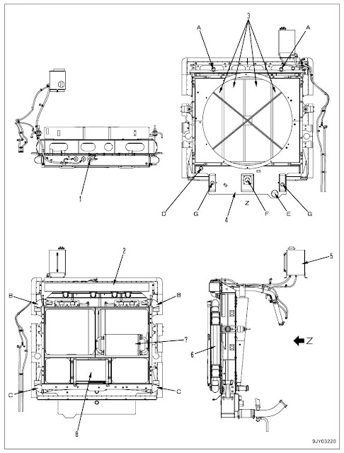
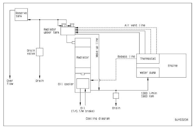
Radiator, brake, torque converter oil cooler, aftercooler, steering, hoist oil cooler

Radiator, brake, torque converter oil cooler, aftercooler, steering, hoist oil cooler


Radiator, brake, torque converter oil cooler, aftercooler, steering, hoist oil cooler diagram


1. Pick up for radiator coolant level sensor
2. Upper tank
3. Radiator core
4. Oil cooler (brake, torque converter)
5. Reservoir tank
6. Aftercooler (engine intake air)
7. Air conditioner condenser
8. Steering hoist oil cooler
A: Coolant inlet port (From engine)
B: Aftercooler inlet port (From turbocharger)
C: Aftercooler outlet port
(To engine air intake manifold)
D: Coolant bypass inlet port (From engine)
E: Coolant outlet port (To water pump)
F: Oil inlet port (From rear and front brakes)

G: Oil outlet port (To transmission)


Specifications
1. Radiator
Core type: 5 lines of aluminum waved tube
Total radiation surface: 334.8 m2

2. Torque converter, transmission, brake oil cooler
Core type: PTO-LS
Total radiation surface: 16.26 m2

3. Steering hoist oil cooler
Core type: CF40-1
Total radiation surface: 5.18 m2

4. Aftercooler
Total radiation surface: 85.8 m2
Air conditioner

Gas charge weight (HFC-134a): 900 ± 50 g


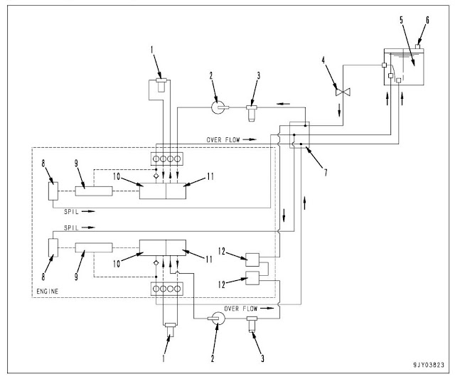
Fuel system 1 

(Standard specification)

HD785-7 Fuel system 1 (Standard specification)


  1. Fuel filter
  2. Priming pump
  3. Fuel pre-filter (with water separator)
  4. Valve
  5. Fuel tank
  6. Breather
  7. Block
  8. Injector
  9. Common rail
  10. Supply pump
  11. Feed pump
  12. Fuel cooling plate


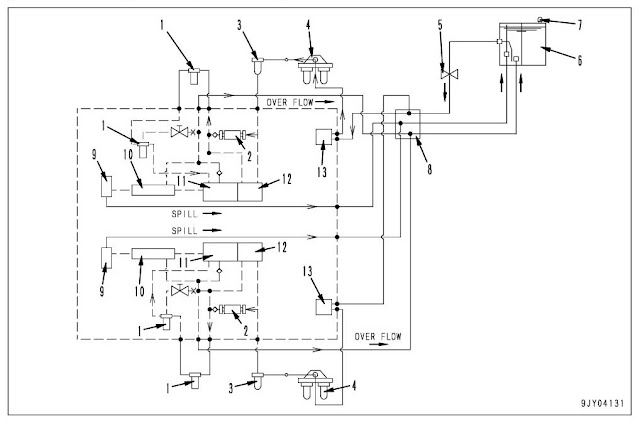
(Poor fuel arrangement specification)

HD785-7 Fuel system 1 (Poor fuel arrangement specification)


  1. Fuel filter
  2. Electric priming pump
  3. Fuel pre-filter (with water separator)
  4. Water separator
  5. Valve
  6. Fuel tank
  7. Breather
  8. Block
  9. Injector
  10. Common rail
  11. Supply pump
  12. Feed pump
  13. Fuel cooling plate


HD785-7 SPECIFICATION

HD785-7 SPECIFICATION

Compatible Unit Serial Number : 7001 and up 

Introduction:

​The Komatsu HD785-7 continues the tradition for this iconic truck. Known globally as the leading 100 tonne class truck due to its outstanding productivity and reliability, the HD785-7 through latest technology adoption continues to outperform all competitors.

The HD785-7 meets our customer’s demands through superior;
  • Payload
  • Engine Horsepower
  • Component quality and technology

 Quality and Reliability to deliver customer outcomes.

Komatsu rigid dump truck HD785-7


SPECIFICATION AND TECHNICAL DATA

Specification Drawing

Komatsu HD785-7 Specification Drawing

Machine Model : HD785-7
Serial No. : 7001 and up

Power Train
1. Torque Converter
  • Structure : 3-element, 1-stage, 2-phase
  • Lock- up clutch : Hydraulically actuated, wet-type, multiple-disc clutch
2. Transmission
  • Type : TORQFLOW planetary gear. Fully automatic, electrically-hydraulically actuated, force-feed type pump.
  • No. of speeds : F7, R2
3. Reduction Gear
  • Type : Spiral bevel gear, splash lubrication
  • Reduction ratio : 3.357
  • Differential type : Straight bevel gear, splash lubrication
4. Final Drive
  • Type : Planetary gear, splash lubrication
  • Reduction ratio : 6.333


Steering System
  • Type : Fully hydraulic steering system

Suspension

1. Axle type
  • Front axle : Independent suspension (Mac Pherson type)
  • Rear axle : Full floating
2. Suspension method
  • Front axle : Hydropneumatic (Automatic damping force selection type)
  • Rear axle : Hydropneumatic

Tires
1. Size and No.
  • Front tire : 27.00R49**E4
  • Rear tire : 27.00R49**E4
2. Tire pressure
  • Front and rear tire : 686 {7} kPa {kg/cm2}


Brake System
1. Service brake
  • Front Brake : Oil cooled multiple disc brake, Hydraulically controlled
  • Rear Brake : Oil cooled multiple disc brake, Hydraulically controlled
2. Parking brake
  • Multiple disc wet type disc brake, Hydraulically released spring type
3. Retarder
  • Oil cooled multiple disc type, Hydraulically controlled

Hydraulic System
1. Hydraulic pump
     - For both steering and work equipment
  • Type : Gear pump
  • Delivery (at engine rated speed 1,900 rpm) : 580 l/min
     - For charging torque converter
  • Type : Gear pump
  • Delivery (at engine rated speed 1,900 rpm) : 380 l/min
     - For brake cooling
  • Type : Gear pump
  • Delivery (at engine rated speed 1,900 rpm) : 580 l/min
2. Cylinder
     - Hoist cylinder
  • Type : 2-stage piston type (only 2nd stage: double-acting)
  • No. 1st bore x stroke - 2nd bore x stroke : 2 - 215 mm x 1,045 mm - 180 mm x 1,040 mm
     - Steering cylinder
  • Type : Piston type, double acting
  • No. - bore x stroke : 2 - 110 mm x 475 mm


Weight Table

Note: This weight table is a guide for use when transporting or handling component.
Machine model
HD785-7
Serial Number
7001 and up
Engine assembly
Output shaft assembly
Radiator assembly
Fuel tank
Torque converter
Transmission assembly
Drive shaft assembly (front)
Drive shaft assembly (rear)
Rear axle assembly
. Differential
. Final drive (one-side)
. Rear brake (one-side)
Front axle (one-side) (with A frame, knuckle arm)
Front brake (one-side)
Front suspension cylinder (one-side)
Rear suspension cylinder (one-side)
Frame assembly (with rear support, mount bracket )
Cab assembly
Operator’s seat
Steering cylinder (one-side)
Hoist cylinder (one-side)
Demand valve
Steering valve
Hoist valve
Hydraulic pump (SAR180+180+1)
Hydraulic pump (SDR100+100+SAR25)
Hydraulic pump (SAR180+180)
Dump body
3,365
171
920
495
626
1,812
42
211
10,930
1,127
2,870
1,170
2,530
742
706
246
9,194
1,585
45
87
336
66
24
63
49
46
45
15,200


Fuel, Coolant and Lubricants

  • ASTM: America Society of Testing and Material


Engine oil pan
Transmission
case
Steering,
hoist oil tank
Front
suspension
Rear
suspension
Specified capacity (liters)
134
368
270
29.8 each for
right and left
16.5 each for
right and left
Refill capacity (liters)
129
205
175
-
-


Brake sub tank
Differential case
Final drive case
Fuel tank
Cooling system
Specified capacity (liters)
36
137
64 each for right and left
1,308
283
Refill capacity (liters)
36
137
64 each for right and left
-
279

Notice
Use only diesel fuel.
The engine mounted on this machine employs electronic control and a high-pressure fuel injection device to obtain good fuel consumption and good exhaust gas characteristics. For this reason, it requires high precision for the parts and good lubrication. If kerosene or other fuel with low lubricat-ing ability is used, there will be a big drop in durability.

Note 1: SAE0W30EOS and SAE5W40EOS must be fully synthetic and HTHS (High-Temperature High-Shear Viscosity @ 150 °C), specified by ASTM D4741 must be equal to or higher than 3.5mPa-S(3.5cP).
Komatsu EOS0W30 and EOS5W40 are the most suitable oils.

Note 2: Power train oil has different properties from engine oil. Be sure to use the recommended oils.

Note 3: Hyper grease (G2-T, G2-TE) has a high performance.
When it is necessary to improve the lubricating ability of the grease in order to prevent squeaking of pins and bushings, the use of G2-T or G2-TE is recommended.

Note 4: Supercoolant (AF-NAC)
a. The coolant has the important function of preventing corrosion as well as preventing freezing. Even in the areas where freezing is not an issue, the use of antifreeze coolant is essential. Komatsu machines are supplied with Komatsu Super coolant (AF-NAC). Komatsu Super coolant (AFNAC) has excellent anticorrosion, antifreeze and cooling properties and can be used continuously for 2 years or 4,000 hours.
Komatsu Super coolant (AF-NAC) is strongly recommended wherever available.

b. For details of the ratio when diluting super coolant with water, see "Mixing rate of water and super coolant".
When the machine is shipped from the factory, it may be filled with coolant containing 30% or more
Super coolant (AF-NAC). In this case, no adjustment is needed for temperatures down to -10°C (14°F). (never dilute with water)
When temperature is below -10°C (14°F), adjust the ratio of Super coolant and water, see "Mixing rate of water and super coolant".

c. To maintain the anticorrosion properties of Super coolant (AF-NAC), always keep the density of Super coolant between 30% and 68%.


Mixing rate of water and super coolant
Min. atmospheric temperature
°C
-10
-15
-20
-25
-30
°F
14
5
-4
-13
-22
Amount of antifreeze
Liters
83.7
97.65
111.6
125.55
139.5
US Gal
22.113
25.799
28.484
33.170
36.855
Amount of water
Liters
195.3
181.35
167.4
153.45
139.5
US Gal
51.597
47.911
44.226
40.540
36.855
Volume ratio
%
30
35
40
45
50